Fair Dice Tester (Pt. 1)
Introduction
For fun, I tried my hand at casting some resin dice. They turned out alright, but had quite a few air bubbles (as expected, since I didn’t use a pressure pot). Additionally, I did some hand-sanding to clean up some of the edges and I got curious if this affects the fairness of the die at all. Therefore, for more fun, I decided to throw together this automated dice roller.
Construction
I used a cheap 28BYJ-48 stepper motor & ULN2003-based driver board I had laying around, controlled by a BluePill (STM32F103-based Arduino-like board).
The die itself is held in a plastic cup which is held by a rubber band. This way, by pulling the cup to one side then releasing, the die will get shaken-about inside the cup. I used Wooden popsicle sticks connected to the shaft to pull and release the cup (with a little piece of tape for the popsicle sticks to slot into) and it works surprisingly well.
Earlier attempts and things to watch out for
“Finger” to pull down the cup
Initially, I used a clay “finger” to wrap around the stepper’s shaft (I used clay instead of e.g. 3D printing because I was too impatient to wait for a 45min print). This worked alright, but it was a little bit flexible so it would sometimes fall off the shaft. Also, I forgot that I wanted 3-4 “fingers” on the rotating part so that I could roll faster (the stepper motor is not that fast and takes a few seconds to complete a revolution). When I was taking measurements to make “version 2” of clay fingers, I just grabbed the nearest object I could see to note the length I wanted the finger to be, and that nearest object was a popsicle stick. This turned out really well because, coincidentally, it was exactly half the popsicle stick, so I decided to just drill out a slot (drill 2 holes right next to each-other and use a knife/diagonal cutters to smooth it out) in the center of the popsicle stick and wedge that onto the motor shaft.
“Spring”
For the “springy” mechanism, the most important thing to keep in mind is the low torque capability of the stepper motor. I don’t have an exact number, but I was teetering on the edge of the motor’s torque capabilities. I also tried using steel wire (you can see it’s what I used to position the cup/rubber band relative to the table), but ultimately I couldn’t configure this in a way that had a sufficiently low spring constant. In the end I found the rubber band was a pretty good level of springiness so I just kept it.
Stepper Motor Speed & Homing
For the motor itself, keep in mind that going at a faster (almost max) speed will reduce its torque and cause it to slip. I actually ended up taking advantage of this by creating a “startup”/”homing” procedure where I would spin the motor really fast and it would always get caught at the same place on the cup. Then I would know exactly what part of the rotation the motor was at. This is kind of like homing motors using “bump stop” current sensing detection, but instead if just assumes the motor will harmlessly keep slipping until the homing procedure (with fixed duration) is done.
Using a stepper motor library with acceleration can be helpful in moving faster speeds without slipping during the acceleration up to that speed.
I programmed a speed profile that goes fast when not in contact with the cup, then slows down as it needs to pull down the cup against the rubber band. Then upon release, it speeds up again until the next pull-down. I programmed these as open-loop durations/angles and didn’t use any current feedback or anything like that. In combination with the “homing” procedure laid out, this works very well considering how simple it is.
BluePill & ST-Link v2 connection issues
Finally, I think I had only used the BluePill once or twice before (usually I opt for Arduino Nano since I have tons just lying around) but I decided to take this simple project as an opportunity to play with it a bit more. I also wanted to try out PlatformIO for the same reason - I had only used it 2 or 3 times before and I wanted to get some more familiarity with them both.
I spent a short while trying to figure out why things the BluePill connect (using my knockoff ST-LINK v2). Specifically, when I connected my knockoff ST-Link v2 and BluePill, I would get some device (ST-Link v2) showing up as a USB device, but none of the ST-Link v2 flashers would connect to it. st-info --probe was indicating a device of 0x00 or something like that. Finally, I realized that my knockoff ST-LINK v2 has a different pinout than the official ST-LINK v2. That was a stupid mistake! I realized this by powering up the STM32/BluePill with a USB and realizing that it does have a built-in LED power indicator light, then probing the jumper wires from the ST-LINK v2 to realize it wasn’t giving power, and finally realizing the pinout was completely wrong. I had just google’d “ST-LINK v2 pinout” but actually my clone (“Baite”) had a different pinout: 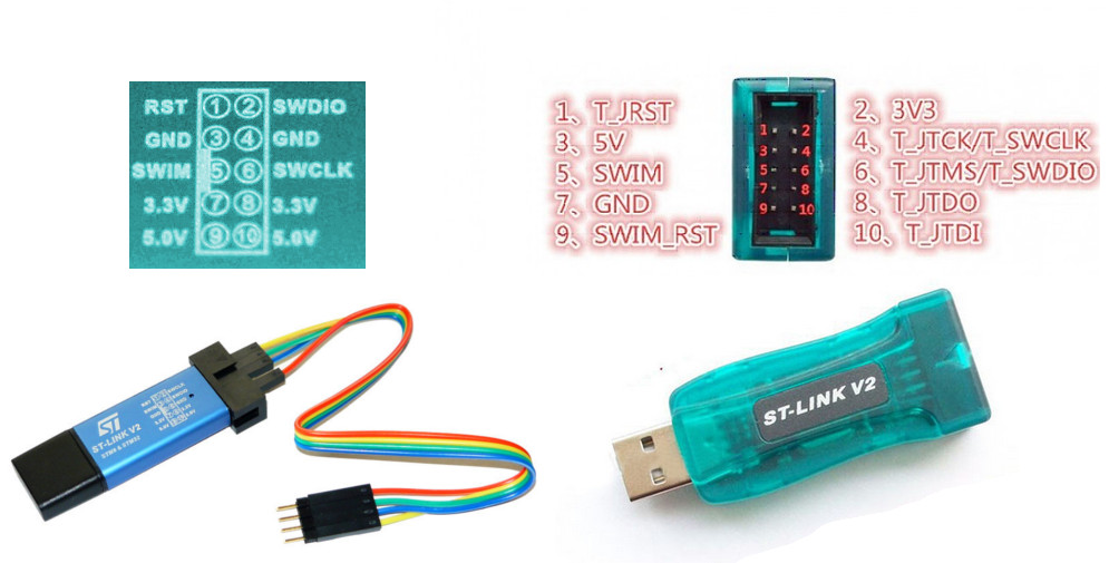
Next Steps
In the next part, I will go through the computer vision used for automatically recording which die was rolled. I had spent a couple hours on this but it wasn’t working very well so I’m going to return later when I have more time.